VVF12 - Fluid humidity calculation in a cylinder
| Flow boundary conditions | Test case |
|---|---|
| Case1 | SVTEST184 |
| Case2 | SVTEST185 |
| Case3 | SVTEST186 |
| Case4 | SVTEST187 |
Description
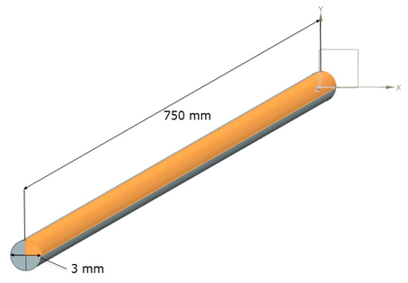
This test case examines the mixing of water vapor in air inside a cylinder and determines the temperature and relative humidity of the mixture at the exit of the cylinder. Two streams of wet air with different values of relative humidity, inlet temperature, and mass flow rate are injected into the cylinder shown in the figure below. A high level of mixing is induced in the cylinder so that the fluid becomes homogeneously mixed before reaching the cylinder outlet.
Geometry
The geometry is made up of a cylinder with 750 mm in length and 3 mm in diameter. One quadrant face is defined and then extruded. The remaining 3 quadrants are formed by revolving the first quadrant. This results in a cylinder with 4 quadrants of equal dimensions, shown in the following figure.
Simulation Model
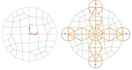
Four separate meshes are defined on the inlet end of the cylinder, so that each quadrant has its own mesh, allowing different mass flow rates, humidity levels, and inlet temperatures to be assigned to each quadrant. The swept mesh is used to create a hexahedral elements mesh along the length of the cylinder. The two quadrants from opposite ends of the cylinder are selected as the source and the target faces. Mesh controls of 3 elements per edge per quadrant side are applied, and can be seen in the figure below. Mesh controls of 75 elements per edge are applied to the 5 edges running the length of the cylinder.
The fluid is modeled using incompressible air with the following properties:
- Mass density: ρ= 1.207 kg/m3
- Thermal conductivity: k = 0.0263 W/m·K
- Dynamic viscosity: µ = 1.85e-005 kg/m·s
- Specific heat at constant pressure: Cp= 1007 J/kg·K
- Coefficient of thermal expansion: β = 0.00341 1/K
- Gas constant: R = 287 J/kg·K
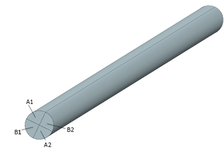
Two wet air streams (A and B) enter at one end of the cylinder. Each stream has two inlet regions denoted by 1 and 2 in the figure below. The two regions of a single stream are diagonally opposite each other. This ensures good mixing of moist air, while keeping the geometry simple. Both streams enter with a swirl angle of 45 degrees but in opposite directions.
The following boundary conditions are applied:
- Flow Boundary Condition: Inlet Flow on four surfaces of the cylinder with external conditions listed in the table below
- Flow Boundary Condition: Opening on the four surfaces at the opposite end of the cylinder
Case ΦA (%) ṁA (kg/s) TA (°C) ΦB (%) ṁB (kg/s) TB (°C) Mass ratio 1 80 1.0e-4 13 20 5.0e-5 36 2/1 2 60 6.0e-5 25 10 1.1e-4 42 6/11 3 90 5.0e-5 17 10 5.0e-5 21 1/1 4 60 1.3e-4 8 20 3.0e-5 40 13/3 where:
- TA and TB are the inlet temperature of stream A and B, respectively.
- ṁA and ṁB are the mass flow rate of stream A and B, respectively.
- ΦA and ΦB are the relative humidity of stream A and B, respectively (ratio of the mass of water vapor to the mass of saturated vapor).
The following solution options are set:
- Turbulence Model: Mixing Length
- Solution Type: Steady State
The default solver parameters are used.
Theory
The state of the homogeneous fluid mixture resulting from the mixing of two streams of wet air can be obtained theoretically with the use of psychrometric charts as shown in the following figures. A psychrometric chart allows all the parameters of the air mixture to be determined knowing initial temperature, relative humidity, and mass flow rate of each stream of air at the inlet point [2].
Adiabatic mixing of two air streams is governed by the mass and energy balances:
- Mass of dry air is defined as:
- Mass of water vapor is defined as:
- Energy is defined as:
where:
- ṁA, ṁB, ṁM are the mass flow rate of stream A, stream B, and mixture M, respectively.
- ωA, ωB, ωM are the specific humidity of stream A, stream B, and mixture M, respectively (ratio of the mass of water vapor to the mass of dry air).
- hA, hB, hM are the enthalpy of stream A, stream B, and mixture M, respectively.
Eliminating ṁM gives the following:
From these balances, it can be shown that the state of the mixture M (TM, ṁM, ωM) lies on a straight line connecting states A (TA, ṁA, ωA) and B (TB, ṁB, ωB) on the psychrometric chart (figures below). The ratio of the distances AM and MB is equal to the ratio of mass flow rate ṁA and ṁB. The first figure below demonstrates the mixing process for case 1. Air stream A, with flow rate of 0.0001 kg/s at 13°C and relative humidity of 80%, is mixed with air stream B, with flow rate of 0.00005 kg/s at 36 °C and relative humidity of 20%.
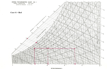
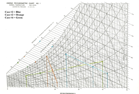
The mass ratio of the two streams of air for case 1 is 2/1. Under these conditions, point M, representing the mixture, is located on the line AB and has the following temperature:
From the chart, the relative humidity, ΦM, is 49.5% and enthalpy, hM, is 39.7 kJ/kg.
Results
The following table compares temperature and relative humidity values of the mixture, predicted by the thermal flow solver with the theoretical results calculated from the equation presented above for TM and from psychrometric charts. The computed results are in agreement with the theoretical values.
| Case | Mass ratio | ΦM,th(%) | ΦM,sim (%) | Errorφ (%) | TM,th (ºC) | TM,sim (ºC) | ErrorT (%) |
|---|---|---|---|---|---|---|---|
| 1 | 2/1 | 49.50 | 49.04 | 0.93 | 20.67 | 20.67 | 0.00 |
| 2 | 6/11 | 20.28 | 20.26 | 0.10 | 35.97 | 35.97 | 0.00 |
| 3 | 1/1 | 45.55 | 45.46 | 0.20 | 19.00 | 18.99 | 0.05 |
| 4 | 13/3 | 50.25 | 49.98 | 0.53 | 14.00 | 14.02 | 0.14 |