VVF18 - Turbulent flow over cylinder
| Test case |
|---|
| SVTEST196 |
Description
This validation case examines the turbulent flow over a circular cylinder with uniform cross-section. The turbulent flow is simulated for a Reynolds number of 65240, which corresponds to the inlet velocity of 5m/s. This case compares the drag force and drag coefficient results computed by the flow solver with the theoretical results.
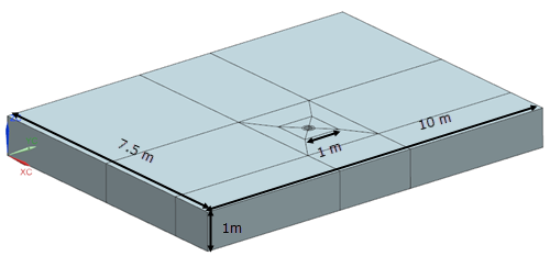
Geometry
The geometry consists of an extruded rectangular fluid domain with a cylindrical cavity. The cavity diameter, D, is 0.2 m. The length of the calculation domain in the Z-dir is 1 m. The domain sizes in X and Y directions are 7.5 m and 10 m, respectively.
This model uses the Advanced Flow solution type.
The swept mesh is made of hexahedral elements. The calculation domain is partitioned into 20 sections.
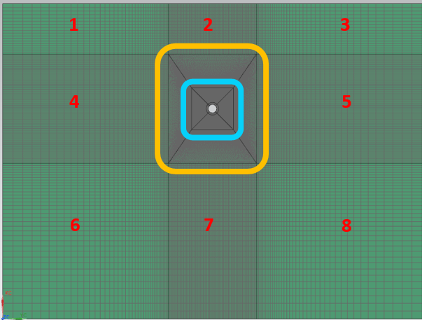
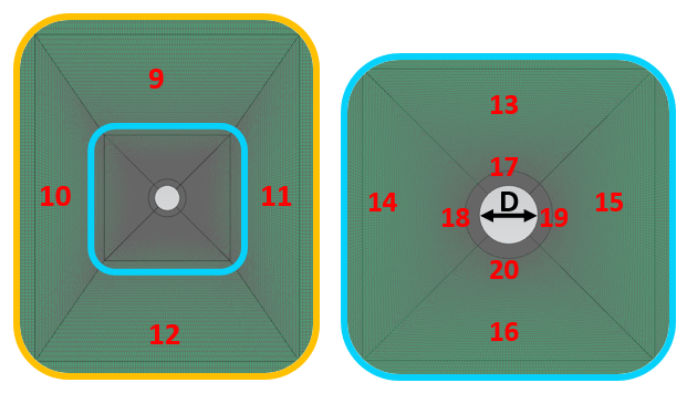
The number of elements used in the + Z-dir is 2 without any bias. The following table describes the mesh controls used in the model.
| Section | Position | Number of elements | Bias factor | Edge fraction |
|---|---|---|---|---|
| 1 and 3 | X | 18 | start of edge=1.04 | 1 |
| Y | 40 | start of edge=1.06 | 1 | |
| 2 | X | 18 | start of edge=1.04 | 1 |
| Y | 100 | no bias | - | |
| 4 and 5 | X | 100 | no bias | - |
| Y | 40 | start of edge=1.06 | 1 | |
| 6 and 8 | X | 35 | start of edge=1.04 | 1 |
| Y | 40 | start of edge=1.06 | 1 | |
| 7 | X | 35 | start of edge=1.04 | 1 |
| Y | 100 | no bias | - | |
| 9 and 12 | top and bottom sides | 100 | no bias | - |
| left and right sides | 35 | start of edge=1.04 | 1 | |
| 10 and 11 | left and right sides | 100 | no bias | - |
| top and bottom sides | 35 | start of edge=1.04 | 1 | |
| 13 and 16 | top and bottom sides | 100 | no bias | - |
| left and right sides | 65 | start of edge=1.0225 | 1 | |
| 14 and 15 | left and right sides | 100 | no bias | - |
| top and bottom sides | 65 | start of edge=1.0225 | 1 | |
| 17 and 20 | top and bottom sides | 100 | no bias | - |
| left and right sides | 60 | start of edge=1.068 | 1 | |
| 18 and 19 | left and right sides | 100 | no bias | - |
| top and bottom sides | 60 | start of edge=1.068 | 1 |
Total number of elements in the model: ~ 163 K
Total number of nodes in the model: ~ 246 K
The fluid is modeled using incompressible air with the following properties:
- Mass density: ρ = 1.207 kg/m3
- Dynamic viscosity: µ = 1.85e-5 Pa·s
- Specific heat at constant pressure: Cp = 1007 J/kg·K
The following boundary conditions are applied:
- Symmetry Plane on the two XY planes.
- Symmetry Plane on the two XZ planes.
- Flow Surface: Boundary Flow Surface on the surface of the cylindrical cavity with No Slip Wall conditions.
- Flow Boundary Condition: Inlet Flow on the topmost wall (+ X-dir) with velocity of 5 m/s with the intensity of 0.01 and eddy length of 0.278 mm (computed from the eddy viscosity ratio of 0.01) set in the Turbulence Characteristics modeling object.
- Flow Boundary Condition: Opening on the bottommost wall (- X-dir) with the same Turbulence Characteristics modeling object as for inlet flow.
- Report Lift and Drag on the cylinder face.
The following solution options are set:
- Turbulence Model: SST - Shear Stress Transport
- Solution Type: Transient
- Transient Setup: Time step = 0.001 s; start time = 0s; end time = 6 s
- Results sampling: at constant time intervals = 0.01 s
- Initial conditions: Uniform with velocity of 0 m/s and the same Turbulence Characteristics modeling object as for inlet flow.
The following solution parameters are set:
- 3D Flow Solver: RMS residual = 1e-5
- 3D Flow Solver: Transient - Iteration Limit = 50
- 3D Flow Solver: Advection scheme for Momentum set to Second-order (SOU)
Theory
Schlichting [38] provides the drag coefficient of circular cylinders as a function of Reynolds number. At the Reynolds number of 65240, the drag coefficient is equal to 1.2. The drag force is computed as follows:
Results
The following figures show the drag force and drag coefficient on the cylinder versus time.
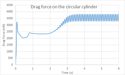
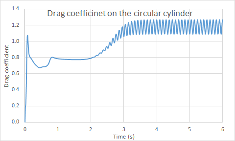
The following table compares the average drag force and drag coefficient results computed by the flow solver for the last 2 seconds of the simulation with the theoretical results.
| Parameters | Theory | Flow solver | Difference,% |
|---|---|---|---|
| Drag force, N | 3.621 | 3.530 | 2.51 |
| Drag coefficient | 1.2 | 1.17 | 2.5 |