Immersed boundary method
The flow solver can use the immersed boundary method based on the ghost-cell method to discretize and solve CFD equations. This method allows you to implement boundary conditions for the immersed boundaries without modifying the overall finite-volume algorithms.
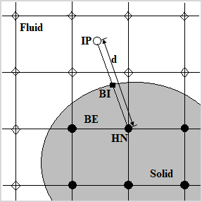
In this method, the occurrence of the immersed boundary is introduced at the halo nodes (HN). Halo nodes belong to immersed boundary elements (BE) and coincide with the solid node. A boundary element in the immersed mesh is a cell that contains part of both the solid body and the fluid domain. The flow variables at the halo nodes are calculated to implicitly satisfy the wall boundary condition using the values at the body intercept points (BI) on the immersed boundary and at the image points (IP). The image point is created by extending a line normal to the immersed boundary, from the halo node to the body intercept point, such that the body intercept point lies at the midpoint of the line connecting the halo node, and the image point. The values near the boundary are calculated using the value at the halo nodes with the appropriate finite difference schemes.
The general variable, ϕ, at an image point, is obtained using trilinear interpolations in an explicit or implicit fashion:
where α is the interpolation coefficient.
The flow solver calculates variables at the halo nodes using linear interpolation between the known values at the image point, and the assigned boundary condition (Dirichlet or Neumann) at the immersed body surface.
The Dirichlet boundary condition assigns the value of the variable at the body intercept, ϕBI.
A linear interpolation implies that:
Based on the previous equations, the value on the halo node for Dirichlet boundary condition is computed as follows:
The Neumann boundary condition assigns the normal derivative at body intercept point.
The central difference method implies that:
where d is the distance between the halo node and the image point node.
Based on these equations, the value on the halo node for Neumann boundary condition is computed as follows:
Depending on the type of boundary condition, one of the two equations for ϕHN replaces the conservation equation for the halo node in the linear system.
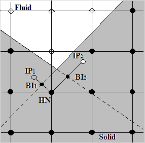
The trilinear interpolation scheme is used for the image point of the halo node that is located in the fluid region only. If both an image point and a halo node are located in the solid region, for example, a sharp concave corner geometry as shown in the following figure, the versatile sharp interface immersed boundary method is used [56].