Disjoint mesh pairing
The flow solver needs to control the fluxes across the interface between two disjoint meshes. The interface is a coplanar face pair where the nodes and elements of the associated fluid meshes are not coincident.
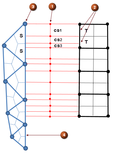 |
(1) Control surface (2) Sub-faces (3) Source node (4) Unmapped face |
The schematic depicts the interface between the source and target sides with the different element types. Each element face is divided into many sub-faces (2) using integration points: sub-faces S for the source side and sub-faces T for the target side. The sub-faces from the source side and the target side are overlapped creating intersecting control surfaces csi (1). The area contribution fraction of each control surface is evaluated based on the intersection of the control surface (1) with the sub-face (2). When there is no intersection between source and target element faces, the unmapped element face is treated as a wall (4).
The area fraction of the sub-face S contributing to the sub-face T is given by:
The area fraction of the sub-face T contributing to the sub-face S is given by:
So that
where:
- csi is the ith control surface.
- SS is the area of the sub-face of the source element face.
- ST is the area of the sub-face of the target element face.
The solver uses these area fractions for transferring conserved fluxes such as advection, diffusion, mass etc. from one mesh to the other. Conserved fluxes on each control surface are computed as follows:
- The fluxes of the face elements on each side (FS, FT) are first computed independently.
The flux of a control surface Fcsi is an area average of the two fluxes:
The FS and FT are the implicit and conserved fluxes that are normally computed on a face. The previous equation redistributes an average of the computed fluxes on both sides.
The redistributed fluxes, Fcsi, are then added to their target nodes on each side. Therefore, the implicit fluxes added to the equations on each side are:
The advection fluxes across the interface between two disjoint meshes are first-order accurate.
With this redistribution procedure, the following conditions are automatically satisfied to define a conservative transfer of fluxes through the interface.
where:
- n is the number of control surfaces to overlap the sub-face S.
- m is the number of control surfaces to overlap the sub-face T.
Pressure drop due to flow through the screen on disjoint meshes
The flow solver computes the pressure drop due flow through the screen on disjoint meshes based on average velocity Uaverage across disjoint fluid mesh pairing:
where h is the total head loss coefficient.
Then, ΔP is added as a surface term (pressure force) to the momentum equations on the disjoint fluid mesh pairing interface.