VVC8 - Natural convection from a horizontal cylinder
| Geometry | Temperature constraint | Test case |
|---|---|---|
| Model 1 | 22.93 | SVTEST101 |
| 47.95 | SVTEST102 | |
| 298.15 | SVTEST103 | |
| Model 2 | 22.93 | SVTEST104 |
| 47.95 | SVTEST105 | |
| 298.15 | SVTEST106 |
Description
This case examines the natural convection heat transfer from a long heated horizontal cylinder at a uniform and constant temperature in the free air. To cover a wide range of Rayleigh numbers, the temperature difference between the heated cylinder and the free air is varied from 2.78 ºC to 278 ºC. Two models are analyzed. The first model has a cylinder internal diameter of 50 mm and the second model has a cylinder internal diameter of 230 m. This provides a Rayleigh number range of 3.5 x 10⁴ to 3.5 x 10⁸.
Geometry
The geometry consists of a solid cylinder. It is modeled as a solid thin layer (thin shell). The average diameter of the cylinder is used to define the geometry and thickness (distance between outer and inner diameter of cylinder).
The following table summarizes the geometry dimensions for the two models.
| Cyl ID, mm | Cyl OD, mm | Cyl Ave. D, mm | X, left to right, mm | Y, bottom to top, mm | Z, air depth, mm | |
|---|---|---|---|---|---|---|
| Model 1 | 50 | 55 | 52.5 | 350 | 750 | 50 |
| Model 2 | 230 | 250 | 240 | 1440 | 3600 | 200 |
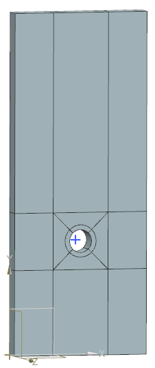
The following figure shows the general analyzed geometry. A short length of the cylinder is modeled between two symmetry planes, which define the air volume.

Simulation model
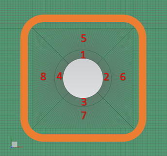
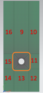
The swept mesh is made of hexahedral elements. The calculation domain is partitioned into 16 sections as shown:


The following table lists the mesh controls used for model 1.
| Section | Position | Number of elements | Bias factor | Edge fraction |
|---|---|---|---|---|
| 1 -4 | on the circle | 20 | no | |
| normal to circle | 8 | 0.98 | 1 | |
| 5-8 | on the circle | 20 | no | |
| normal to circle | 16 | 0.98 | 1 | |
| 9 | X | 20 | no | |
| Y | 50 | 0.97 | 1 | |
| 10 and 16 | X | 12 | 0.94 | 1 |
| Y | 50 | 0.97 | 1 | |
| 11 and 15 | X | 12 | 0.94 | 1 |
| Y | 20 | no | ||
| 12 and 14 | X | 12 | 0.94 | 1 |
| Y | 20 | 0.92 | 1 | |
| 13 | X | 20 | no | |
| Y | 20 | 0.92 | 1 |
The following table lists the mesh controls used for model 2.
| Section | Position | Number of elements | Bias factor | Edge fraction |
|---|---|---|---|---|
| 1 -4 | on the circle | 40 | no | |
| normal to circle | 16 | 0.98 | 1 | |
| 5-8 | on the circle | 40 | no | |
| normal to circle | 32 | 0.98 | 1 | |
| 9 | X | 40 | no | |
| Y | 100 | 0.985 | 1 | |
| 10 and 16 | X | 24 | 0.98 | 1 |
| Y | 100 | 0.985 | 1 | |
| 11 and 15 | X | 24 | 0.98 | 1 |
| Y | 40 | no | ||
| 12 and 14 | X | 24 | 0.98 | 1 |
| Y | 40 | 0.98 | 1 | |
| 13 | X | 40 | no | |
| Y | 40 | 0.98 | 1 |
The following material properties are selected:
- Mass density: air - ρ = 1.204 kg/m3 , aluminum - ρ = 2794 kg/m3
- Thermal conductivity: air - k = 0.0263 W/m·K
- Dynamic viscosity: air - µ = 1.85e-005 kg/m·s
- Specific heat at constant pressure: air - Cp = 1007 J/kg·K
- Coefficient of thermal expansion: β = 3.41e-3 K-1
- Gas constant: air - R = 287 J/kg·K
The following boundary conditions are applied:
- Flow Boundary Condition: Opening on the four edges of the fluid domain.
- Symmetry Plane on the front and on the back faces of the fluid domain.
- Flow Surface: Boundary Flow Surface on the average diameter of the convecting cylinder, using the No Slip Wall option with smooth wall friction and convection properties set to Automatic.
- Temperature constraint: on the cylinder, based on the values in °C listed in the following table.
| Case | 1 and 4 | 2 and 5 | 3 and 6 |
|---|---|---|---|
| T | 22.93 | 47.95 | 298.15 |
The following non-default solver options are used:
- Turbulence Model: None (Laminar Flow)
- Solution Type: Steady State
- Buoyancy: Selected
- Ambient Conditions: Fluid temperature = 20.15 °C , pressure = 0.101351 MPa
The following non-default solver parameters are used:
- 3D Flow Solver: Physical steady-state with time step = 20 s
- 3D Flow Solver: Maximum Residuals = 5e-4
- 3D Flow Solver: Buoyancy Model=Boussinesq
- 3D Flow Solver: Advection Schemes group: Momentum - SOU with limiter 0.5, Energy - SOU with limiter 0.5
- 3D Flow Solver:Relaxation Factors group: Global = 0.25, Mass = 0.25, Fluids = 0.6
Theory
The Nusselt number for natural convection, from a long heated horizontal cylinder at the uniform constant temperature in free air is given by the following correlation [43]:
where m is equal to 10.
The Nusselt number for laminar flow is computed as follows:
where f = 0.8 for. Ra > 10−4 and NuT is defined as:
where Cl is equal to 0.515 for air.
The turbulent Nusselt number is given by the following equation:
where Ct = 0.103 for circular cylinders in the air.
The Nusselt number calculated by solver is obtained from the following equation:
where:
- Q is the total heat flow from the cylinder to the air.
- D is the cylinder average diameter.
- A is the cylinder surface area.
- k is the air thermal conductivity.
The cylinder surface area is calculated as:
where L is the air fluid depth.
Results
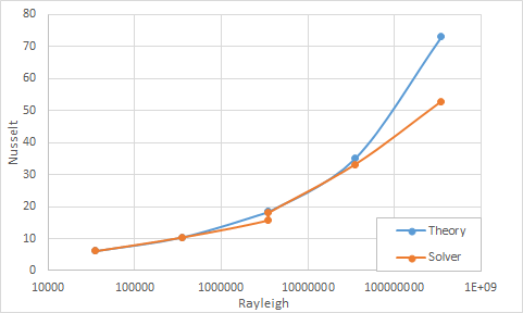
The following table and graph compare the average Nusselt numbers predicted by the solver for Rayleigh numbers ranging from 3.5 x 10⁴ to 3.5 x 10⁸ to empirical values.
| Case | D (m) | ΔT (ºC) | Ra | Nul | Nut | Nu(Corr) | Nu(sim) | Error (%) |
|---|---|---|---|---|---|---|---|---|
| 1 | 0.0525 | 2.78 | 35·103 | 6.204 | 3.370 | 6.205 | 6.428 | 3.60 |
| 2 | 0.0525 | 27.8 | 35·104 | 10.45 | 7.259 | 10.477 | 10.907 | 4.10 |
| 3 | 0.0525 | 278 | 35·105 | 17.985 | 15.638 | 18.386 | 16.596 | 9.74 |
| 4 | 0.24 | 2.78 | 35·105 | 17.985 | 15.638 | 18.386 | 18.817 | 2.34 |
| 5 | 0.24 | 27.8 | 35·106 | 31.373 | 33.692 | 35.063 | 34.65 | 1.18 |
| 6 | 0.24 | 278 | 35·107 | 55.176 | 72.587 | 73.042 | 55.275 | 24.32 |

