View factor calculation algorithm
The following outlines the steps by which view factors are calculated without ray-tracing using deterministic method without explicit sky modeling.
- Non-ray-traced view factors are calculated individually for each element pair i and j.
- Orbital view factors are calculated from the viewing element i to the internal representation of the environmental source (the planet or the sun), which is considered to be element j.
- Heat flux view factors are calculated from viewing element i to the radiative source elements j.
Step 1: viewing check
Before calculating view factors or orbital or heat flux view factors, a viewing check is performed. The vertices of element i are examined to see whether they can be seen by the front surface of element j. Similarly, the vertices of element j are examined to see if they can be seen by element i. Both conditions need to be met for the elements to see each other. Lump mass elements cannot view each other if their nodes are coincident. Beam elements cannot view each other if their axes fall on the same straight line.
Step 2: preliminary view factor magnitude check
A preliminary view factor magnitude check is performed for view factor and heat flux view factor (but not solar view factor) calculations to see if the view factor is too small to be calculated. The minimum acceptable threshold in the solver, and defaults to 1.E-10.
Step 3: preliminary shadowing check
If calculations with shadowing are requested, an initial shadowing check is performed on the shadowing surfaces to screen out shadowing surfaces that cannot possibly block the view of one element to the other. Only shadowing surfaces that contain elements that belong to the enclosure are considered for screening. For this calculation, lump mass and beam elements are transformed into equivalent rectangles.
Each shadowing surface is subjected to the following tests:
- A clipping test in which a rectangular box is created around the two viewing elements, using their maximum and minimum global coordinates. If the maximum and minimum coordinates of the shadowing surface fall outside the box, it cannot possibly shadow.
- The shadowing surface's vertices are examined to see if they fall behind the front surface of either of the viewing elements. If they do, the surface cannot shadow.
- If the vertices of both viewing elements fall on the same side of the shadowing surface, the surface cannot shadow.
Step 4: calculating view factors with no shadowing
If there are no shadowing surfaces between the elements i and j, the elements are not subdivided, and a special algorithm for computing unshadowed view factors is used to calculate the view factor VFij between them. The algorithm uses various techniques depending on the types of elements involved.
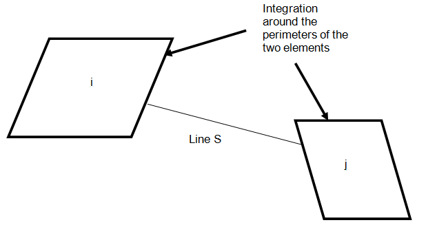
If both viewing elements i and j are planar, VFij is calculated with the contour integral technique. This technique yields very accurate view factors. It consists of numerically integrating the following double integral around the perimeters of the two elements:
where:
- Ci and Cj are the paths around the perimeters of elements i and j.
- S(Ci,Cj) is the length of a line between two points on the perimeters of elements i and j.

If the plane of element i cuts the plane of j, the shape of the cut element is modified to ensure the integration is performed only over the edges of the portions that see each other.
View factors for spherical lump mass elements are calculated with an analytical expression without subdividing the sphere's surface into sub-elements.
View factors for beam elements are calculated by transforming them into equivalent surface area hexagonal tubes and using the exact contour integral technique with the planar sides.
Once the view factor is calculated, if the solver requests heat flux view factors, the view factor is multiplied by the POWER and POWERIR values, where POWER is the value of the solar spectrum heat load per unit time emitted by the source elements and POWERIR is the IR spectrum heat load per unit time emitted by the source elements.
Step 5: calculation of the subdivision parameter
If possible shadowing surfaces have been found in Step 3, each element i and j are subdivided as discussed previously.
The subdivision parameter may be user-specified or automatically calculated. For this option, the subdivision parameter, MESH, is calculated by:
If j is not a space element:
If j is a space element:
where:
- ERR is the maximum view factor sum error:
where VFij is the view factor from element i to element j. ERR must be between 0 and 1.
- VFi is the maximum approximate estimated view factor between i and j, where element i is the smaller element.
- NV is the average of the number of vertices of the elements i and j.
The subdivision parameter values are rounded off to the nearest integer.
Step 6: viewing and blockage checks for sub-elements
If some shadowing surfaces have been identified as possibly shadowing, each element i and j is subdivided, and the incremental view factors DVFij from each sub-element DAi to each sub-element DAj are calculated. The subdivision is governed by the Card 6f MESH parameter in the manner shown above.
For view factor calculations, element i is chosen to be the element with the smaller area.
A viewing check is performed to verify that the front surface of each sub-element DAi can see the front surface of each sub-element DAj.

If the plane of one of the triangular sub-elements cuts through the other sub-element, the shape of the second sub-element is appropriately modified to allow view factor calculations between only those portions that see each other.
If either i or j is warped, then it is checked that the sub-elements are not shadowed by part of the warped element. The angle θ is calculated to be the angle between the vector joining the centroids of the two sub-elements and the surface normal of the warped element. Then:
Next, a blockage check is performed for each of the possible shadowing surfaces by checking if any of them intercepts the line joining the centroids of DAi and DAj. If a shadowing surface blocks, DVFij = 0.
Step 7: Nusselt sphere technique
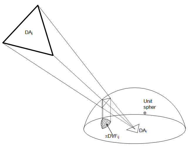
If both i and j elements are planar, and there is no blockage between the sub-elements, the Nusselt sphere technique is used to calculate VFij. The Nusselt sphere technique is used because although it is more approximate than the contour integral technique, it requires much less CPU time.

The Nusselt sphere uses a double projection method. First, a unit sphere (radius=1) is drawn around the centroid of element i, whose area is smaller than element j. Next, the vertices of element j are projected onto the sphere by drawing lines from the center of the sphere to the vertices. These vertex projections are then re-projected from the unit sphere onto the plane of element i.
The area of this second projection is equal to VFij.
The Nusselt sphere technique is most accurate if either element i or element j is far away from the other.
If one of the elements is a beam, VFij is calculated using the exact contour integral technique, not the Nusselt sphere technique, between the sub-elements. This is because beam sub-elements tend to have high aspect ratios, and the assumption of small VFij does not necessarily hold.
The incremental view factors DVFij are then summed to obtain VFij.
If during the shadowing checks it turns out that none of the possible shadowing surfaces does in fact shadow, and both element i and element j are planar, and VFij is sufficiently large, then VFij is recalculated for greater accuracy with the exact contour integral technique.
If heat flux view factors were requested by the solver, the view factors are multiplied by the POWER and POWERIR values.
Step 8: calculation of solar view factors
If solar view factors are requested instead of view factors, an eclipse check is first performed to see whether the planet blocks the sun.
To model the sun, an internal 1-node element is created from the sun angles at a distance of 1.E6 from the origin. The blockage checks between the element i and the sun are performed as discussed above.
If there is no eclipse, the incremental solar view factor for element i to the sun is:
where:
- DSVFi is the incremental solar view factor of sub-element DAi.
- θsun is the angle between the solar vector and the element's surface normal.
1-node elements are not subdivided. For a 1-node element SVFi=0.25.
For a beam element:
where:
- θaxis is the angle between the element's axis and the sun vector.

At the end of the view factor calculation stage, the incremental solar view factors are summed and written as an array of solar view factors SVFi at each time interval.
Step 9: diffuse incident solar spectrum flux from the sky
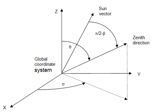
If diffuse sky view factor requested, then the view factor of element i to the diffuse sky as well as to the radiation reflected from the ground is calculated. The calculation is performed in the solar spectrum without any shadowing. The view factor is an equivalent albedo view factor. The thermal solver uses the following equation:
where:
- ALBi is the view factor of element i to the diffuse sky plus the radiation reflected from the ground.
- PSUN is the value of the solar flux attenuated by the atmosphere reaching the surface.
- PSUN2A is the value of the solar flux.
- DIFFSKY is the diffuse sky factor ratio, i.e., the diffuse sky flux on a horizontal plate divided by the direct normal solar flux.
- σ is the surface elevation angle, i.e., the angle between the element surface normal and zenith.
- β is the solar altitude angle in degrees, the angle from the horizontal to the sun vector.
- REFLG is the ground reflectance.
Step 10: view factor merging
View factors may be merged. However, this can significantly reduce the accuracy of radiation calculations because of the problems of non-uniform illumination. If element merging is desired, a preferred approach is to perform element merging, which will maintain the non-uniform illumination properties.
